9- Pre-flight Checks (0.8.4 Kit)

|
🚦 Difficulty Medium |
|
📃 Steps 22 |
|
|
⏲ Estimated Time 40 minutes |
Step 1: Powering the Printer


🟪 Plug the printer into the wall and turn the switch on.
Look for the following:
🟦 Row of LEDs on the Duet should light up
🟩 Driver LEDs should blink red and green, then stay green.
🟨 BLTouch should deploy and retract as it starts up and then stay red.
🟧 Filament switch light should turn on and blink alternating red - green.
⚠If other things happen take note of what and turn the power switch off.
Step 3: Duet UI
🟪
amb-"printer number".local/
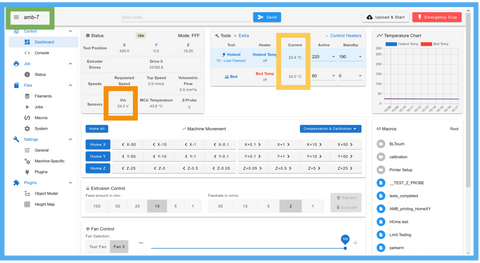
- Go to a browser on a computer on the same WiFi network as the printer.
🟪 Enter in this address, replacing “printer number” with the ID number for the printer.
🟦 The address should take you to this page.
- There should be a filament error you have to clear over the page.
🟩 The name of the printer should be in the upper left corner.
🟨 The two tools in the tool panel should show approximately room temperature.
🟧 Vin should show approximately 24V within 1V
Step 4: Starting the Setup Wizard

🟪 There should be a panel on the right side of the Duet UI with the header “Macros”
If you are accessing Duet UI from a mobile device the layout is different. I recommend using the desktop version of the site for this.
🟦 In the “Macros” section there should be a folder titled “Printer Setup”
- Open the folder.
🟩 There should be a file within the folder titled “Setup Wizard”
- Select the file
🗈The file will start running immediately.
Step 5: Setup Wizard pt. 1- visibility

🟪 After Setup Wizard starts there will be a message pop up on screen to check that you can still see the temperature table behind it, as you will need to see it later.
- If you can see the table, confirm the message.
- If you can’t see the table cancel the message and the setup wizard will exit. Change to the dashboard tab in Duet UI or adjust your screen window so you can see the temperature table before restarting the setup wizard.
Step 6: Setup Wizard pt. 2- endstops


🟪 After the previous message is cleared a new one will pop up to press the proximal switch.
🟦 Press the proximal switch by hand.
- The message should go away.
❌ If the message does not go away the endstop may not be connected.
Check the Status tab to see if the X lights up green when you press the switch.
If it does not there may be an issue with the connection of the switch.
If it does there is something wrong with the Setup wizard. restart the printer and check the firmware version.
🟩 After the proximal message, a new message should pop up saying to press the distal switch.
🟨 Press the distal switch by hand.
- The message should go away.
❌ If the message does not go away the endstop may not be connected.
Check the Status tab to see if the Y lights up green when you press the switch.
If it does not there may be an issue with the connection of the switch.
If it does there is something wrong with the Setup wizard. restart the printer and check the firmware version.
🟧 There should be a new message pop up saying the endstop section passed. Clear this message to go to the next section.
Step 7: Setup Wizard pt. 3- motors


🟪 A new message should pop up saying the proximal arm should move away from the endstop.
🟦 Clear the message and watch the arm.
- The proximal arm should rotate 5 degrees away from the endstop.
❌ If the arm does not move there is something wrong with the wiring or config.g of the printer.
If the distal arm moves the drivers are switched.
If the arm moves towards the endstop the direction of the motor is reversed.
🟩 A new message should pop up saying the distal arm should move away from the endstop.
🟨 Clear the message and watch the arm.
- The distal arm should rotate 5 degrees away from the endstop.
❌ If the arm does not move there is something wrong with the wiring or config.g of the printer.
If the proximal arm moves the drivers are switched.
If the arm moves towards the endstop the direction of the motor is reversed.
🟧 A message should pop up saying the Z should move up.
🟥 Clear the message and watch the arm.
- The Z axis should move up 10mm.
❌ If the arm does not move there is something wrong with the wiring or config.g of the printer.
If the arm moves down the direction of the motor is reversed.
⬛ A message will pop up asking if the motor check passed.
- If so, confirm and continue to the next section.
- The hotend heater will turn on if you confirm.
- If any of the described errors occurred hit cancel and address them.
Step 8: Setup Wizard pt. 4- heaters


🟪 The hotend should start heating up to 50C and a new message will come up.
- Watch the temperature to see if it is going up.
🟦 Watch the hotend fan. It should turn on one the temperature is above 45C.
- If the temperature rises and the fan turns on hit ok.
❌ If the temperature does not rise there is an error in the wiring or config.g with the heater or thermistor.
If the fan does not turn on then there is an error with the wiring or in the config.g with the fan.
🟩 The hotend temperature will change to 200C and the bed heater will turn on to 50C.
- Watch the temperature table to see that both temperatures are rising.
- Wait for the temperatures to settle before continuing.
- If both heaters reach temperature hit OK.
❌ If the bed temperature does not rise there may be an issue with the wiring or config.g of the bed.
If either heater has a fault error then there may be an issue with wiring, config.g setup, or the heater curves in config.g.
🟨 A message will come up saying the extruder check is next.
- Hit ok to go to the next section.
Step 9: Setup Wizard pt. 5- extruder


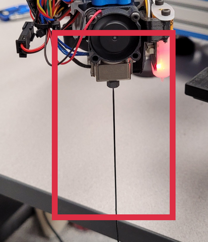

🟪 A message will prompt you to insert filament into the hotend.
- Push the extruder lever to the open position.
🟦 Take a spool of filament and put it on the spool holder.
- Feed the end of the filament through the filament guide.
🟩 Make sure the extruder idler is open by pushing the lever to the far left position.
- Insert the filament into the extruder.
- The light on the filament sensor should turn off.
- Push the filament in until some starts to come out the nozzle.
🟨 Lock the extruder lever in the first engaged position.
🟧 Clear the message in Duet UI.
- A new one will pop up asking if filament is extruding.
🟥 The extruder should start to pull in the filament and start extruding out the nozzle.
❌ If nothing happens then the extruder motor wiring is incorrect, disconnected, or there is an issue in the config.g file.
If the motor ejects the filament back out the extruder, then the motor direction needs to be flipped in the config.g.
- If the extruder successfully extruded filament, clear the confirmation message.
⬛ A message will pop up saying the extruder check is complete.
- Clear the next message to go to the next section.
Step 10: Setup Wizard pt. 6- filament sensor


🟪 A message will pop up asking you to remove the filament from the extruder.
🟦 Push the extruder lever to the open position.
🟩 Pull the filament out of the extruder.
- Look at the light on the filament sensor, while moving filament up or down in the sensor the light should start blinking green rapidly, and alternate between green and red when not moving.
- Clear the instruction message.
❌ Do the above steps, but currently this part of the setup process is broken ever since we moved from a switch sensor to the current magnetic sensor. Unless I have found a way to fix it, no message will pop up after clearing the instruction.
Wait to see if the filament sensor works until the first print at the end of this section, if it doesn’t the print will pause with a filament error.
Step 11: Setup Wizard pt. 7- part fan


🟪 The part fan should turn on.
🟦 Confirm this by either looking under the distal arm or touching the fan.
⚠The hotend is likely still hot at this time.
- If the fan is on confirm.
🟩 Clear the next message to go to the next section.
Step 12: Setup Wizard pt. 8- BLTouch


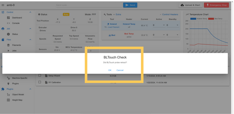
🟪 The BLTouch probe should deploy.
- The probe pin will extend.
- The red light in the BLTouch will turn off.
🟦 Confirm if the probe deployed.
❌ If the probe did not deploy
- Check the connections. There may be an issue with the wiring.
- The BLTouch may simply have a bad connection to the Duet, not necessarily that something is incorrectly wired.
- The BLTouch could be connected to the wrong port on the Duet.
🟩 The probe should retract.
- The pin will retract.
- The red light will turn back on.
🟨 Confirm the BLTouch is working.
❌ If the BLTouch deployed but did not retract.
- The BLTouch could have a weak connection with the Duet.
- It’s possible there is an error in the setup files for the BLTouch in the Duet.
- If the BLTouch retracted confirm the message to go to the next section.
Step 13: Setup Wizard pt. 9- homing


🟪 A message will appear notifying that the printer will home after the message is cleared. Read this sequence before clearing the message.
What should happen:
- Z axis moves up.
- Both joints move towards endstops.
- Joints stop once they reach endstop.
❌ If the joints don’t stop they will error out the drivers, you can see this has happened if a red light starts flashing on the driver.
- Proximal arm moves away from endstop and back to it.
- Distal arm moves away from endstop and back to it.
- Arm moves to the center of the bed.
❌ If the arm moves somewhere else there is a problem in the config file
- BLTouch is deployed
- Z moves down to bed.
- Z stops once BLTouch hits bed.
❌ If the BLTouch does not touch the bed before the nozzle or the BLTouch does not stop the Z then the printer will try to bury the nozzle in the bed. Hit the E-stop button in the UI.
- Z raises up and deploys BLTouch again.
- Z lowers to bed a second time until the BLTouch stops it.
- Z moves up and arm moves to the side of the bed.
🟦 If something in this sequence does not happen, hit the E-stop button in the UI or flip the power switch on the back of the printer off.
🟩 If this sequence happened correctly confirm on the next message.
🟨 Clear the next message to go to the next section.
Step 14: Setup Wizard pt. 10- Z calibration


🟪 A message will pop up and the arm should move the hotend to the center of the bed, just above the bed surface.
- Clear notification message.
🟦 A message will pop up with a jog panel.
🟩 Jog the nozzle up or down until the nozzle is barely touching the bed.
- Take the value the Z shows when the nozzle is touching the bed and write it down.
- This will be used after the setup wizard.
- Clear the jog panel.
🟨 Clear the next message to go to the next section.
Step 15: Setup Wizard pt. 11- XY calibration


⚠Take the bed surface off the printer for these next couple sections.
🟪 A new message will appear and the nozzle will move to the corner of the bed by the circuit case.
🟦 Clear the notification message.
- A jog panel will appear.
- jog the nozzle around so that the center of the nozzle is directly over the corner of the bed.
- Take a note of the XY values for later.
- Clear the jog panel message.
🟩 A notification will appear and the hotend should move up and then away from the circuit case to the next corner.
- Clear the notification message.
- A jog panel will appear.
- jog the nozzle around so that the center of the nozzle is directly over the corner of the bed.
- Take a note of the XY values for later.
- Clear the jog panel message.
🟨 A notification will appear and the hotend should move up and then to the next corner.
- Clear the notification message.
- A jog panel will appear.
- jog the nozzle around so that the center of the nozzle is directly over the corner of the bed.
- Take a note of the XY values for later.
- Clear the jog panel message.
🟧 A notification will appear and the hotend should move up and then to the fourth corner.
- Clear the notification message.
- A jog panel will appear.
- jog the nozzle around so that the center of the nozzle is directly over the corner of the bed.
- Take a note of the XY values for later.
- Clear the jog panel message.
🟥 Clear the next message to go to the next section.
Step 16: Setup Wizard pt. 12- BLTouch XY Calibration


🟪 This is a repeat of step 15, except now you should align the BLTouch probe to the points on the PCB.
🟦 After the section is done a message will pop up saying that the Heater Tuning section is next. Put the print surface back on the printer before clearing the message.
Step 17: Setup Wizard pt. 12- Heater Tuning


🟪 A message will pop up notifying that hotend tuning will start.
- Arm will move to the center of the bed.
❌ The nozzle should not be touching the bed at this time. Cancel the wizard and restart the printer.
You will need to put in the Z height calibration number first.
- The hotend heater will turn on and start tuning.
- This can take 15 minutes. Don’t leave the printer, but you don’t have to watch it closely, just keep the Duet UI open and keep an eye for any error messages.
- Clear the notification message.
🟦 After tuning is finished a message will come up asking if you want to save the tuning to the config.
- Confirm the save to config.
🟩 A new notification message will appear that heated bed tuning will start.
- The z axis will move up.
- The heated bed will turn on and start tuning.
- This will take a while. Don’t leave the printer, but you don’t have to watch it closely, just keep the Duet UI open and keep an eye for any error messages.
🟨 After tuning is finished a message will come up asking if you want to save the tuning to the config.
- Confirm the save to config.
Step 18: Setup wizard complete

🟪 After the notification goes away it should be replaced by a message saying the setup wizard is complete.
- Clear this message.
Step 19: Inputting the Z height value


🟪 In the Duet UI, go to the “System files” tab
🟦 Open the config.g file.
🟩 In the top section of the file, there is a variable named zProbeOffset.
- Take the Z value you took note of in step 14
- subtract the value from the Z value in the variable.
- Example, if you wrote down a value of 0.5, the Z value would now be:
- Z=2-0.5=1.5
- Example, if you wrote down a value of -0.5, the Z value would now be:
- Z=2-(-0.5)=2.5
🟨 Change the Z value in the variable to the new one.
🟧 Save the config.g file.
The following two calibration sections are subject to change as we move the calibration functionality into the UI.
Step 20: Calibrating the Hotend XY


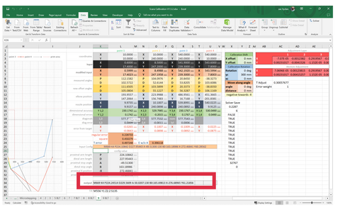

🟪 Go to the scara calibration spreadsheet.
🟦 Input the gathered points into the “Input” rows of the main table.
- Make sure the X values go in the X row and Y values go in the Y row.
🟩 Go to the macros tab of the Duet UI.
- Follow the path: System\AMB\Calibration\AMB_ScaraConfig_HotEnd.g
- Click on the file to edit it.
- Copy the M669 command that is uncommented in the file, leaving out the comment at the end of the line.
🟨 Paste the M669 command into the “input config” box of the calibration spreadsheet.
- The config value table should automatically fill out with the values from the input command.
❌ If the table does not fill out it usually means one of the values has the wrong number of digits.
Each value in the command that is in the table should have five decimal places.
🟧 Go to the Data tab in Excel.
- Open the “Solver” screen.
If you don’t see the solver option you need to enable it in the Excel extensions.
- Hit the “Solve” button in the solver window.
- Wait for the solver to run, a new window will appear when it is finished.
🟥 Copy the “output” box under the config table.
- Paste it into the bottom of the “scara_configuration” file.
- put a comment at the end of the M669 line with the error value of the solver.
🗈The error can range from under 0.1 to over 1 depending on how well the input points are. Lower is better, but under 1 is the target. If it is over 2 there may be something wrong with the input points, input config, or the solver.
- Save the scara_configuration file
Step 21: Calibrating the BLTouch XY

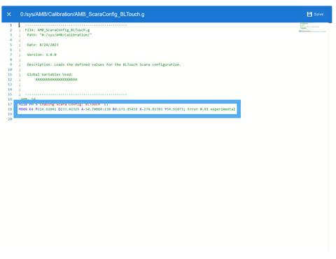
- Repeat the process in step 20, but with the XY coordinates you gathered for the BLTouch.
🟪 After you have the output config from the Excel file, go to the bltouch_configuration file in the calibration folder from last step.
🟦 Paste the output into the file.
🟩 Save the BLTouch configuration.
Step 21: Test print


🟪 On the main dashboard, in the macros list on the right of the screen, click the “toggle M9001” macro.
🗈this macro will toggle whether the HTTP is disabled at the start of a print, we have it set on by default because there are issues with the HTTP connection causing the Duet board to restart.
A message will pop up at the bottom of the screen saying whether it is enabled or disabled. You want it to be disabled for now.
🟦 Go to the “Jobs” Tab in the Duet UI
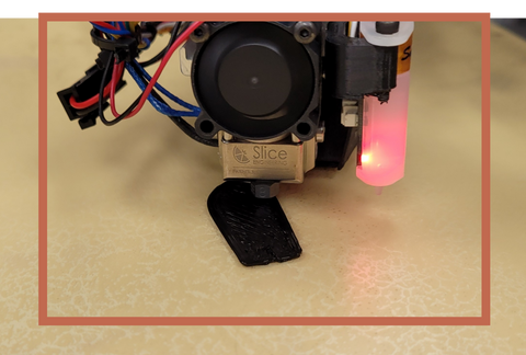
🟩 There should be a preloaded gcode file
🟨 Select it and start the print.
🟧 The Duet UI should go to the status page, and the heaters should start heating up.
🟥 When the print finishes bed leveling you may need to jog the nozzle up or down on the status Page_with the babystepping buttons.
If you do need to babystep the nozzle, you can go back to the config and edit the ZOffset variable to tune the initial offset for future prints.
🟫 Watch the print for the first layer or two (this test print will be fairly short)
- Let the print run until something goes wrong or the print finishes.
- Toggle M9001 back on at the end of the print.
Step 22: All Done

- Congratulations! You’ve successfully assembled a printer! 🎉
