UI Guide

UI Guide

Created by Zac Hyden, last modified on May 14, 2024

🟪 When you first open the UI there is a reminder to make sure you are connected to the same network as the hub and printers to use the UI. Otherwise, you won’t be able to communicate with the system.

🟦 After clearing the reminder you will see the My Environments screen. This screen is where you can save different printer layouts.

  • To get started you need to make a layout.
  • 🟩 1. Type your desired environment name in the input field.

    If there are previously created environments, make sure to type a different name.

  • 2. Press the plus icon button that is next to the input field or press ENTER.
  • 🟨 Now, you’ll see your environment included in the list. You’ll also see three action buttons which are in charge of the following.

    1. Environment Name
    2. Rename
  • As its name states, it renames the environment selected. This functionality includes error checking for cases in which we provide the same environment name as other created environments or names with more than 25 characters.
    1. Layout Settings
  • This button opens up another portal that allows users to configure their desired workspace layout. After configuring the layout the environment will be activated and ready to open.
    1. Delete
  • This button deletes the environment selected.
  • Each button has a tooltip title description if you hover over them.

    🟨 To continue, click on the layout settings button.

    🟧 The layout settings opens the workspace layout screen.

  • This is where you configure your printer layout for the slicer.
  • 🟥 The workspace layout has five elements.

    1. Drop down for layout presets.
    2. Number of printers in X direction (side by side)
    3. Number of printers in Y direction (face to face). This has a maximum of two.
    4. Confirm your settings.
    5. Save to current environment and close workspace layout screen.

    ⬛ Once you have set up a layout, a new button appears alongside it in the list.

  • This button opens the environment.

  • Part 2: UI Sections

  • Once you have opened an environment, you will be taken to the main UI screen.
  • Environment Selection

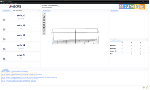
    🟪 The upper bar of the UI shows the current environment you have selected.

  • You can click the folder icon to be taken back to the Environment selection screen to select a different environment, change the settings of the current one, or make a new one.
  • Navigation Bar

  • To the right of the current environment, there are seven icons.
  • 🟪 Upload file

    🟦 Hub Watcher

    🟩 Gcode Sender

    🟨 Slicer Settings

    🟧 Printer Calibration

  • This section details the use of these buttons.
  • 🟪 Upload Files

  • This button opens a panel to send the current build plate to the Hub for processing.
  • There are two checkboxes in this panel.
  • Auto send to Printers: If checked the hub will upload the processed gcode file to the selected printers automatically, there is no reason to uncheck this unless you are bugfixing the hub.
  • Enable Supports: Needs to be checked if you are printing a file with a slicer profile that has supports enabled. The hub processes files with supports slightly differently than without.
  • The Job Nick Name box allows you to name the print job to change how it shows up in the “My Print Jobs” list.
  • The Upload button at the bottom of the panel sends the build plate to the hub.
  • 🟦 Hub Watcher

  • Opens up a panel with three general sections.
  • At the top of the panel you can see:
  • The UI IP is the IP address the UI is on.
  • The Hub IP is the IP address the hub is on.
  • To the right of the IP addresses is a box that you can input the IP address and ID of a hub if it does not auto-connect and connect to it manually.
  • Below the IP addresses the drop down lists all previously connected Hubs to allow you to switch between them.
  • The Reconnect button will try to reconnect to the hub selected in the drop down.
  • The ReSearch Hubs button will search the network for a Hub.
  • The Reboot Hub button sends a reboot command to the connected hub.
  • The Shutdown Hub button sends a shutdown command to the hub.
  • The Update Hub button sends an update command to the hub.
  • The reboot command should auto-reconnect to the UI.

    The shutdown command will require you to press the power button on the Hub PC to start it.

  • To the middle of the panel there is a list of process names with an icon next to start and stop buttons. This is the list of process nodes on the hub and their status. If they are shut down a symbol will be next to it and if they are running a ✅ symbol will be next to them.
  • PreProcessor: Handles the processing of uploaded files.
  • Maincomm: Handles the coop logic for each print job. This node cannot be started manually as it is launched by the user hitting the “start print” button.
  • Interweaver: Takes the files from the Slicer Node and post-processes them into the final gcode files that will be sent to the printer.
  • Recovery: Handles the recovery of the hub in case of failure.
  • Slicer: Slices the files output from the PreProcessor.
  • Scanner: Scans the network for communications from the UI and connected printers.
  • Chuck Checker: Checks the output of the PreProcessor node for missing sections of the file.
  • Slicer Checker: Checks the output of the slicer node for missing sections of the file.
  • Interweaver Checker: Checks the output of the Interweaver node for missing sections of the file.
  • Printer Calibration: Handles the printer calibration functions.
  • At the bottom of the hub watcher panel are two buttons.
  • Start Hub Nodes: Sends a command to the hub to start all the nodes. (Note that the Maincomm will not start with this since it is only started with a print job.)
  • Kill Hub Nodes: Sends a command to the hub to kill all started hub nodes.
  • 🟩 Gcode Sender

  • This panel allows you to select a connected printer to send individual gcode commands to it.
  • 🟨 Slicer Settings

  • There are a set of buttons at the top of this panel.
  • Import slicer config to UI.
  • Export slicer config from UI.
  • Save current config to UI.
  • Delete clears the config from the UI.
  • Get Config’s From HUB downloads the current configs on the Hub.
  • Send Config’s To HUB sends the config in the UI to the hub.
  • Note: The hub currently has just two save slots for slicer settings, one for printing with supports and one for without supports.

    Printer List

    🟪 The Printer List is a panel on the left of the UI that lists all the printers currently connected to the hub.

  • This panel allows you to see the status of each printer, what area of the environment they are assigned to, and gives you access to some basic functions for the individual printers.
  • 🟦 Printer Assignment

  • This is a drop-down list that allows you to select which build area the printer is assigned to.
  • For a single printer print, this is just selecting which printer will print the model.
  • For a coop print, this is assigning the placement of the printers next to each other, and must reflect how the printers are physically set up.
  • 🟩 Printer Settings

  • This is a page each printer has in the printer list and is accessed by clicking on the name of the printer.
  • This panel holds the following functions, listed top-down.
  • printer status
  • printer position
  • hotend temperature
  • bed temperature
  • setting hotend temp
  • setting bed temp
  • Home XY & Home all
  • My Print Jobs List

    🟪 The My Print Jobs tab next to the my printers tab lists the currently uploaded print jobs.

    🟦 Each print job has a card with information and controls.

    Controls listed top to bottom, left to right:

  • Row 1:
  • Job name
  • Rename job button
  • Delete job button
  • Row 2:
  • Job status
  • Row 3:
  • groups of four numbers.
  • First two numbers in a group is the printer position.
  • Second two numbers in a group is the printer ID.
  • Example: 11 13 is the printer in position coordinate 1,1 and is occupied by bot 13.
  • Row 4:
  • Start
  • Pause
  • Cancel
  • Restart
  • The print control buttons are green when you can click on them and grey when they are unavailable.

    Workspace

    🟪 The center section of the UI is the workspace.

    🟦 To the left side of the workspace is a row of buttons. The functions of these buttons is detailed below.

    🟩 The main area of the workspace is the 3D environment where you will set up print jobs.

    Upload Model

  • Opens file browser to upload a STL model into the workspace.
  • Export Model

  • Exports the current workspace as an stl file.
  • Delete

  • Deletes the currently selected model.
  • Move

  • When a model is selected, this switches the model gizmo to move mode for dragging the model around with the mouse.
  • Rotate

  • When a model is selected, this switches the model gizmo to rotate mode for rotating the model with the mouse.
  • Scale

  • When a model is selected, this switches the model gizmo to scale mode for stretching the model in each axis.
  • Auto Scale

  • Scales the model to the largest size that fits on the bed.
  • This does not rotate the model, so it scales until one dimension is the maximum build volume in the current orientation of the model.

    Auto Center

  • This button centers the model in the build volume in XY and places it on the bed in Z.
  • You may have to press autocenter twice for the model to be placed on the bed.

    Model List

    🟪 Lists the models loaded into the workspace.

    🟦 Current model selected is highlighted in the model list and in the workspace.

    🟩 You can select a different model by clicking on it’s name in the model list or by clicking on the model in the workspace.

    🟨 The check boxes next to the model names allow you to hide them in the uploaded job without deleting them from the workspace.

    Model Transform Table

    🟪 This table allows you to see the position, rotation, scale, and size of the current model selected.

  • You can modify the model through this table as a more precise alternative to the model gizmos.
  • Console

    🟪 This shows the sequence of actions taken by the UI.

  • This is also where error messages will appear.
  • Connection Status Icons

    🟪 There are two icons on the lower right of the UI.

  • The left icon is green when the UI is connected to the internet.
  • The right icon is green when the UI is connected to a hub.
  • UI Section Resizing

    There are two ways to resize the panels in the UI.

    🟪 Clicking the box in the corner puts the panel in full screen.

    🟩 You can also click and drag the edges of the panels to resize them.


    2- Print Process

    Part 1: Loading a model

    🟪 Click the “upload model” icon in the workspace.

    🟦 Select the STL file for printing from your file browser.

  • Arrange the file how you want it to be printed using the model gizmos and/or the model transform table.
  • Make sure the model is on the bed by pressing the Autocenter button. If the model is not on the bed an error will be given.


    Part 2: Assigning printers

    🟪 Go to the printer in the “my printers” list that you want to print the model.

    🟦 Click the location assign drop down and assign the printer to the build area.

    Note: when doing a cooperative print the assignments for the printer locations must match the arrangement of the physical printers.


    Part 3: Checking the Hub

    🟪 Click on the “hub watcher” icon

    🟦 In the hub watcher panel, confirm that you are connected to a hub (or the correct one if you have multiple), by checking that there is a hub ID & IP address and that they are correct.

  • If no hub is shown, check the connection icons at the bottom of the UI to see if the UI is connected to the internet.
  • 🟩 If the hub nodes are shut down, click the “start hub nodes” button at the bottom of the panel.


    Part 4: Uploading the File

    🟪 Once you are ready to print, click on the “upload files” button in the navigation bar.

    🟦 Check that “Auto send to printers” is checked.

    “Auto send to printers” should only be unchecked if you are testing the hub.

  • Select or deselect “enable supports” depending on if you want supports generated for this print.
  • 🟩 Click the “upload” button to send the print to the hub.


    Part 5: Hub processing file

  • After clicking the Upload button, the UI will initialize the file processing.
  • A series of loading bars will appear at the bottom of the UI to show the hubs progress.
  • 🟪 Uploading to hub shows the progress of uploading the .stl file to the hub.

    🟦 Chunking Model is the process for cutting the uploaded model into chunks.

    🟩 Slicing is the process for slicing the file into gcode.

    🟨 Generating gcode is the process of assembling the gcode files for each printer.

    🟧 Uploading to printer is the hub uploading the finished gcode files to the printers.

    🟥 After the process is complete messages will appear in the console saying the hub is ready to start the print.

    🟪 Once the file is processed, go to the My Print Jobs tab next to the printer list.

    The job list can take a moment to load in since it is retrieving the list from the hub.

    🟦 Any uploaded jobs will appear in this list with either the nick name you assign them or with the file name and timestamp.

    🟩 Press the green Start button to start the print job.

  • The hub will initialize the job on the printer.

  • Back to blog