AMB C1 Initial Setup

|
🚦Difficulty Medium |
|
📃 Steps 22 |
|
|
⏱ Estimated Time 40 minutes |
Step 1: Handling the Printer
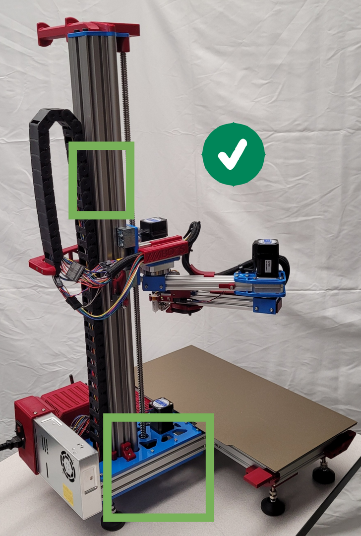

✅ Do:
- Carry the printer with two hands.
- Lift the printer from the arm base and steady it by holding onto the Z Axis rail.
❌ Do NOT:
- Lift the printer by the bed or bed frame.
- Hold onto the Ball screw (try to touch it as little as possible)
- Hold on to the printer by the arm.
- Hold on to the cable chain.
Step 2: Setting up WiFi for the printer
There are three options with this step:
- Connect the printer to your computer and use the AMBOTS connecting assistant.
- Remove the printers SD card and enter the network info into the runonce file.
- Connect the printer to your computer with a USB cable and input the network info over a command line. If you have a micro SD card reader we recommend the SD card option as the simpler choice at this time.
🗈The printers can only connect to 2.4Ghz WiFi channels.
With Connecting Assistant


🟪 Make sure the printer is powered off.
🟦 Download the AMBOTS Connecting Assistant.
🟩 Launch the AMBOTS Connecting Assistant.
🟨 Plug the included micro USB cable into the control board and your computer.
- The status LEDs should light up on the control board.
🟧 Click the refresh button in the connecting assistant.
- There should be a new com port show up in the console.
- Select the new com port in the drop down.
🟥 Input your WiFi SSID and password into the respective boxes.
- Click the “Set up Wi-Fi” button
⬛ The WiFi LED on the Duet should start blinking and go solid once it is connected to the network.
The console in the connecting assistant will also show when the wifi is connected.
- Click the disconnect button in the connecting assistant.
- Unplug the printer from your computer.
With SD card


🟪 Make sure the printer is powered off.
🟦 Eject the SD card from the control board by pressing the card into the slot until it releases and pulling out the card.
🟩 Insert the card into your computer.
- In file explorer there will be a similar set of files as shown.
🟨 Open the “sys” folder
🟧 Open the “runonce.g” file into a text editor.
🟥 Look in the line that starts with “M587”
- change the text in quotations after the S parameter to the desired network ID.
- change the text in quotations after the P parameter to the network password.
- Example image would work for a network with ssid network and password 12345
- Save the file.
- Eject the SD card from your computer.
⬛ Insert the SD card back into the printer and continue to the next step.
🗈When you power the printer on the runonce file will run, then be deleted. if it does not connect to your network you will have to put a new runonce file in the SD card or try option #2.
With USB Cable


🟪 Make sure the printer is powered off.
🟦 Download / open a command line interface program.
Pronterface - an old program, but we still use it for this type of use case and have success with it.
🟩 Plug the included micro USB cable into the control board and your computer.
- The status LEDs should light up on the control board.
🟨 Open the command line interface program and connect to the serial port the printer is on.
- The console in pronterface should show that the printer is online once it connects and then start repeating messages that the WiFi module is not connected to anything.
🟧 Run this sequence of commands, one line at a time, replacing the text in the quotations with your network info.
M552 S0
M587 S"your network ID" P"your network password"
M552 S1
Pronterface sends text as all caps by default, so you need to put an apostrophe “ ' “ before each letter that is lowercase.
🟥 The green LED next to the WiFi module should start blinking and go solid green once it is connected to the network.
- Once connected to the network the command line interface should also show a message in the console saying the printer connected to the network with its IP address.
Step 3: Powering the Printer
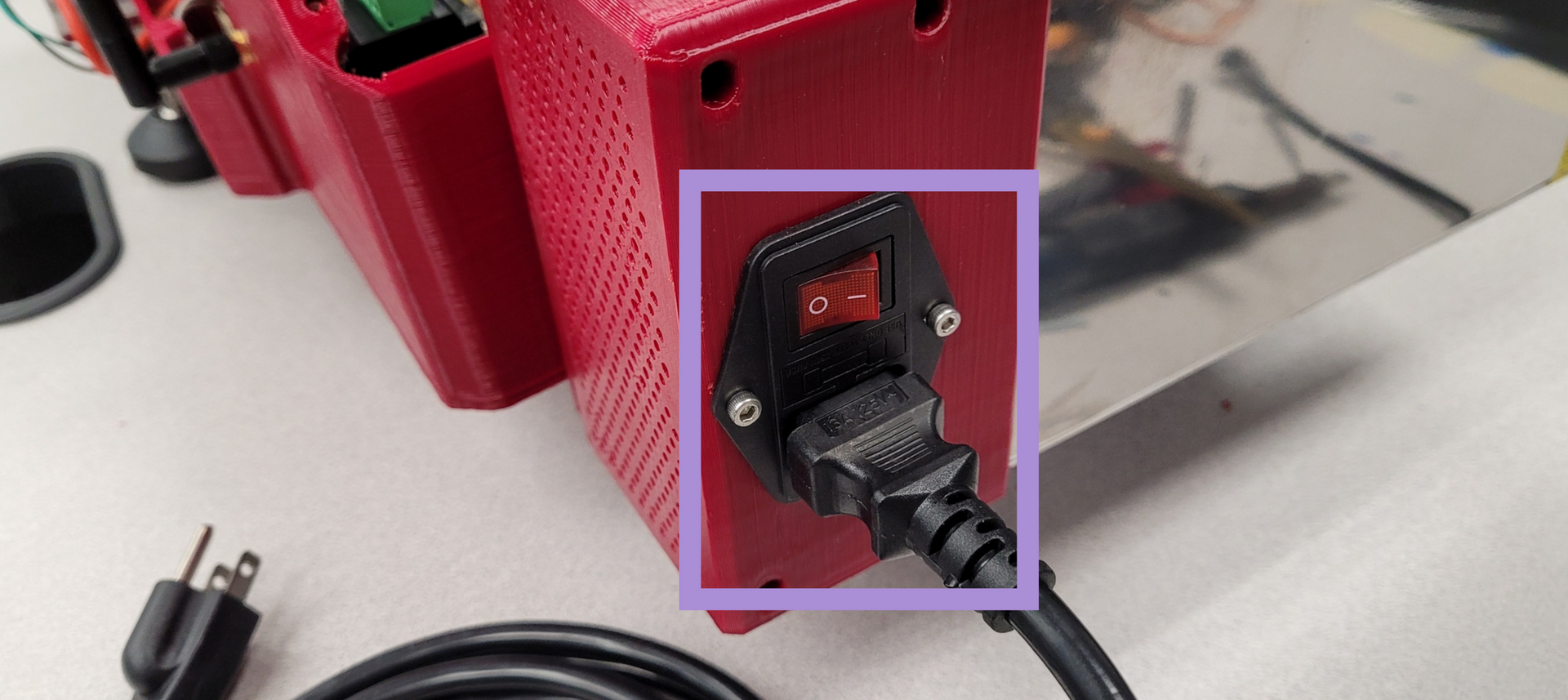


🟪 Plug the printer into the wall and turn the switch on.
Look for the following:
🟦 Row of LEDs on the Duet should light up
🟩 Driver LEDs should blink red and green, then stay green.
🟨 BLTouch should deploy and retract as it starts up and then stay red.
🟧 Filament switch light should turn on.
⚠If other things happen turn the power switch off.
Step 4: Duet UI
🟪
amb-"printer number".local/
- Go to a browser on a computer on the same WiFi network as the printer.
🟪 Enter in this address, replacing “printer number” with the ID number for the printer.
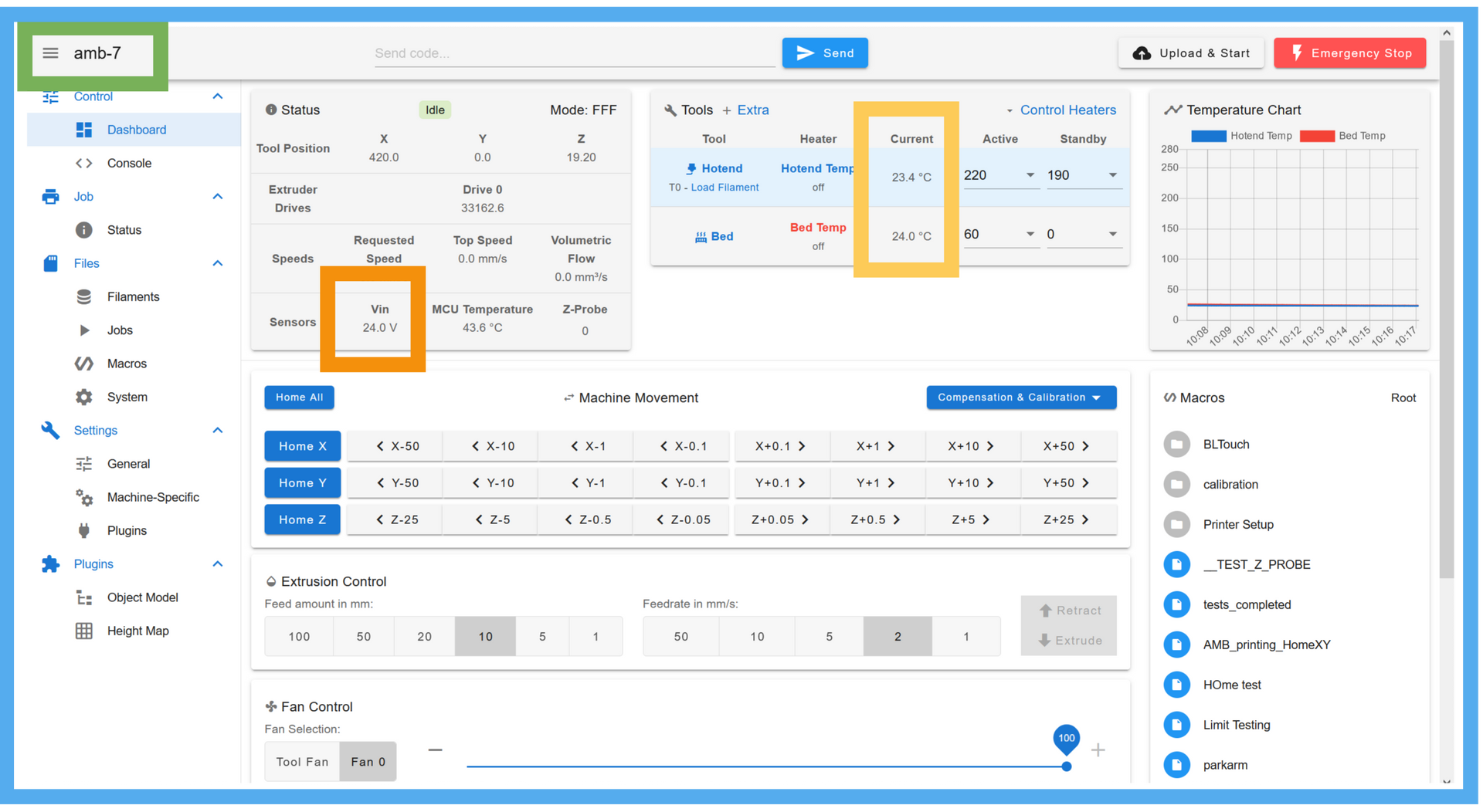
🟦 The address should take you to this page.
- There should be a filament error you have to clear over the page.
🟩 The name of the printer should be in the upper left corner.
🟨 The two tools in the tool panel should show approximately room temperature.
🟧 Vin should show approximately 24V within 1V
Step 5: Starting the Setup Wizard

🟪 There should be a panel on the right side of the Duet UI with the header “Macros”
If you are accessing Duet UI from a mobile device the layout is different. I recommend using the desktop version of the site for this.
🟦 In the “Macros” section there should be a folder titled “Printer Setup”
- Open the folder.
🟩 There should be a file within the folder titled “Setup Wizard”
- Select the file
🗈The file will start running immediately.
Step 6: Setup Wizard pt. 1- visibility

🟪 After Setup Wizard starts there will be a message pop up on screen to check that you can still see the temperature table behind it, as you will need to see it later.
- If you can see the table, confirm the message.
- If you can’t see the table cancel the message and the setup wizard will exit. Change to the dashboard tab in Duet UI or adjust your screen window so you can see the temperature table before restarting the setup wizard.
Step 7: Setup Wizard pt. 2- endstops


🟪 After the previous message is cleared a new one will pop up to press the proximal switch.
🟦 Press the proximal switch by hand.
- The message should go away.
❌If the message does not go away the endstop may not be connected.
Check the Status tab to see if the X lights up green when you press the switch.
If it does not there may be an issue with the connection of the switch.
If it does there is something wrong with the Setup wizard. restart the printer and check the firmware version.
🟩 After the proximal message, a new message should pop up saying to press the distal switch.
🟨 Press the distal switch by hand.
- The message should go away.
❌If the message does not go away the endstop may not be connected.
Check the Status tab to see if the Y lights up green when you press the switch.
If it does not there may be an issue with the connection of the switch.
If it does there is something wrong with the Setup wizard. restart the printer and check the firmware version.
🟧 There should be a new message pop up saying the endstop section passed. Clear this message to go to the next section.
Step 8: Setup Wizard pt. 3- motors



🟪 A new message should pop up saying the proximal arm should move away from the endstop.
🟦 Clear the message and watch the arm.
- The proximal arm should rotate 5 degrees away from the endstop.
❌If the arm does not move there is something wrong with the wiring or config.g of the printer.
If the distal arm moves the drivers are switched.
If the arm moves towards the endstop the direction of the motor is reversed.
🟩 A new message should pop up saying the distal arm should move away from the endstop.
🟨 Clear the message and watch the arm.
- The distal arm should rotate 5 degrees away from the endstop.
❌If the arm does not move there is something wrong with the wiring or config.g of the printer.
If the proximal arm moves the drivers are switched.
If the arm moves towards the endstop the direction of the motor is reversed.
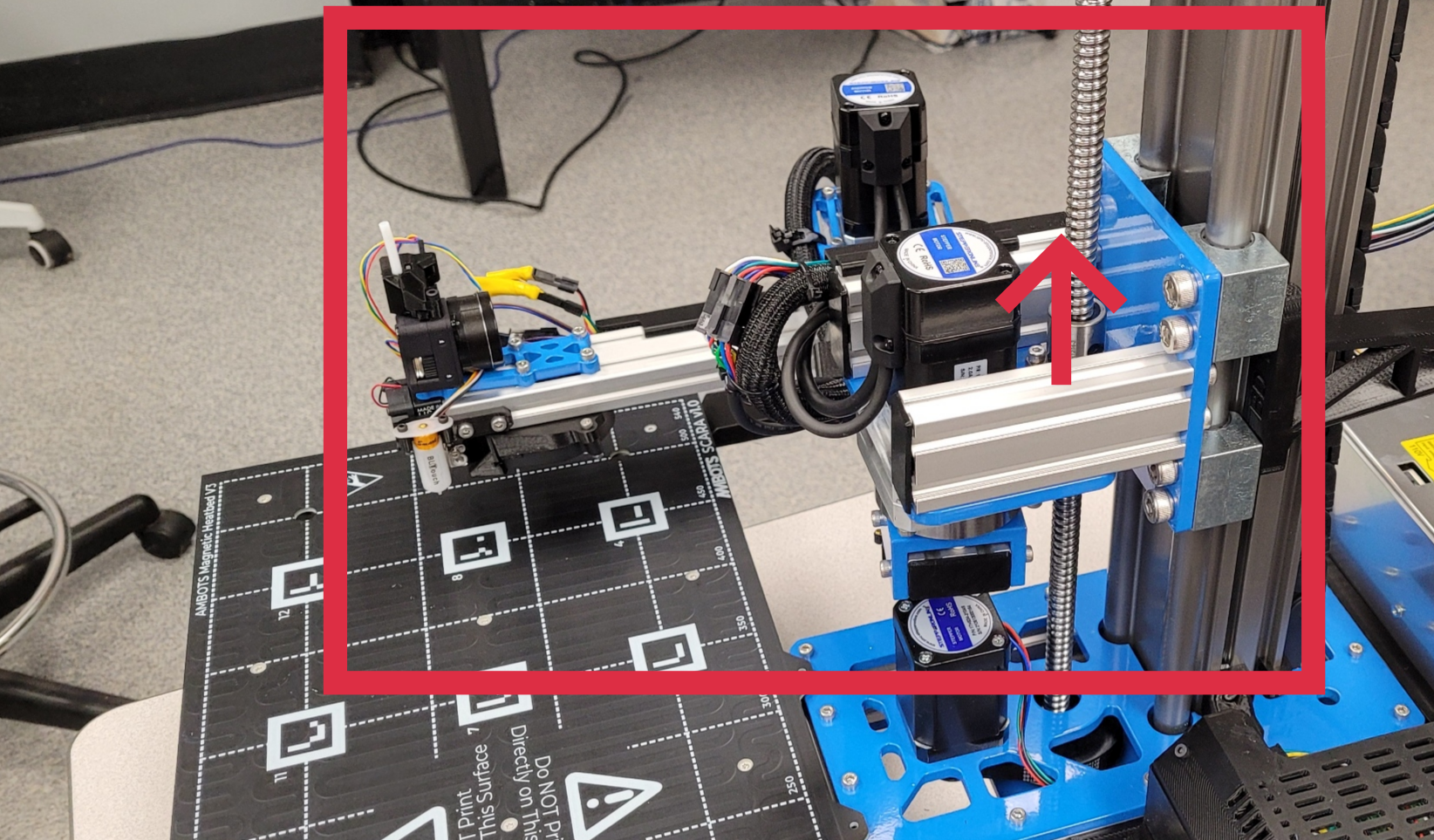
🟧 A message should pop up saying the Z should move up.
🟥 Clear the message and watch the arm.
- The Z axis should move up 10mm.
❌If the arm does not move there is something wrong with the wiring or config.g of the printer.
If the arm moves down the direction of the motor is reversed.
⬛ A message will pop up asking if the motor check passed.
- If so, confirm and continue to the next section.
- The hotend heater will turn on if you confirm.
- The hotend heater will turn on if you confirm.
- If any of the described errors occurred hit cancel and address them.
Step 9: Setup Wizard pt. 4- heaters


🟪 The hotend should start heating up to 50C and a new message will come up.
- Watch the temperature to see if it is going up.
🟦 Watch the hotend fan. It should turn on one the temperature is above 45C.
- If the temperature rises and the fan turns on hit ok.
❌If the temperature does not rise there is an error in the wiring or config.g with the heater or thermistor.
If the fan does not turn on then there is an error with the wiring or in the config.g with the fan.
🟩 The hotend temperature will change to 200C and the bed heater will turn on to 50C.
- Watch the temperature table to see that both temperatures are rising.
- Wait for the temperatures to settle before continuing.
- If both heaters reach temperature hit OK.
❌If the bed temperature does not rise there may be an issue with the wiring or config.g of the bed.
If either heater has a fault error then there may be an issue with wiring, config.g setup, or the heater curves in config.g.
🟨 A message will come up saying the extruder check is next.
- Hit ok to go to the next section.
Step 10: Setup Wizard pt. 5- extruder


🟪 A message will prompt you to insert filament into the hotend.
- Push the extruder lever to the open position.
🟦 Take a spool of filament and put it on the spool holder.
- Feed the end of the filament through the filament guide.
🟩 Insert the filament into the extruder.
- The light on the filament sensor should turn off.
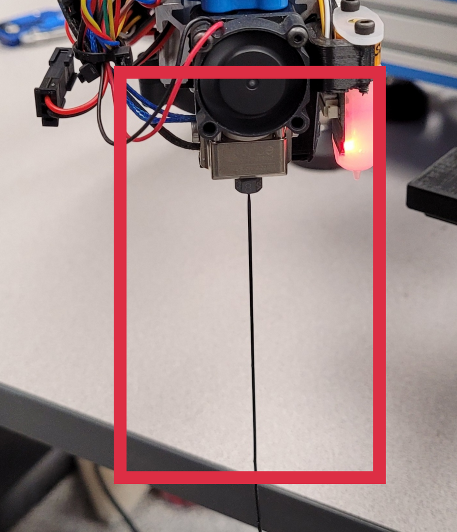
- Push the filament in until some starts to come out the nozzle.
🟨 Lock the extruder lever in the first engaged position.
🟧 Clear the message in Duet UI.
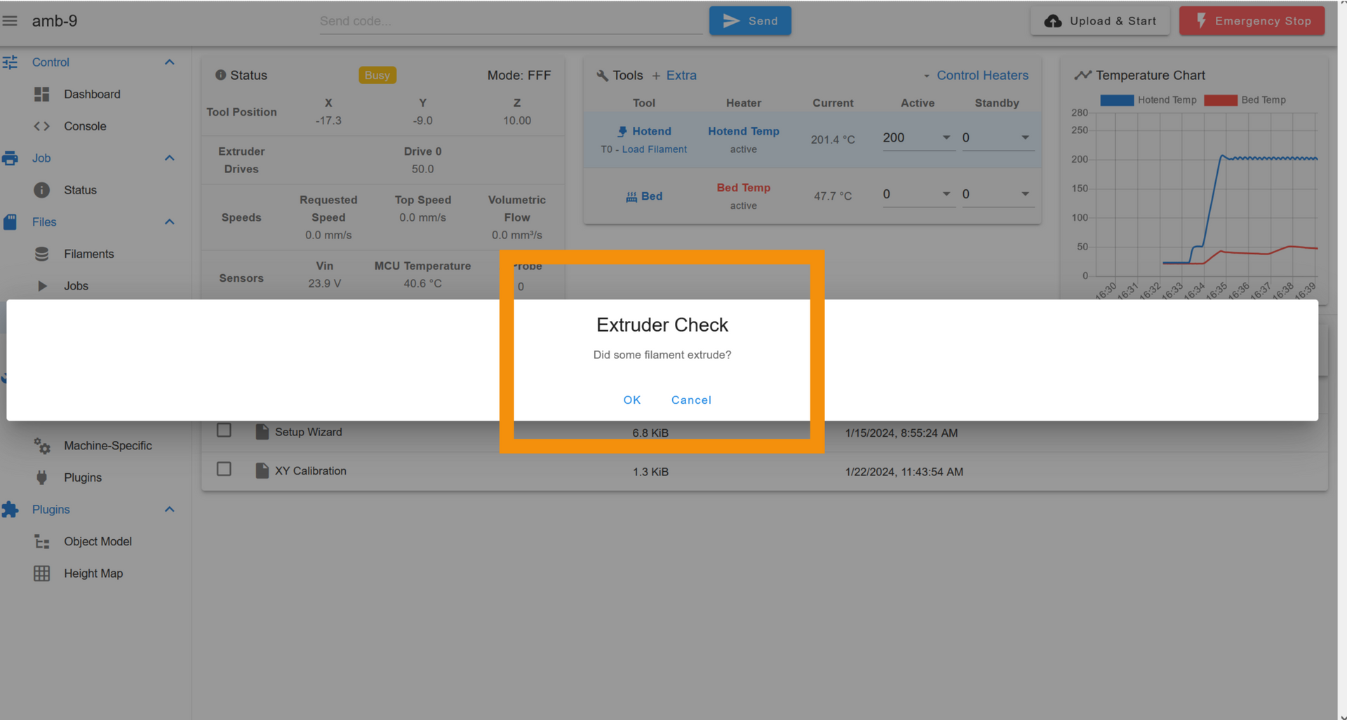
- A new one will pop up asking if filament is extruding.
🟥 The extruder should start to pull in the filament and start extruding out the nozzle.
❌If nothing happens then the extruder motor wiring is incorrect, disconnected, or there is an issue in the config.g file.
If the motor ejects the filament back out the extruder, then the motor direction needs to be flipped in the config.g.
- If the extruder successfully extruded filament, clear the confirmation message.
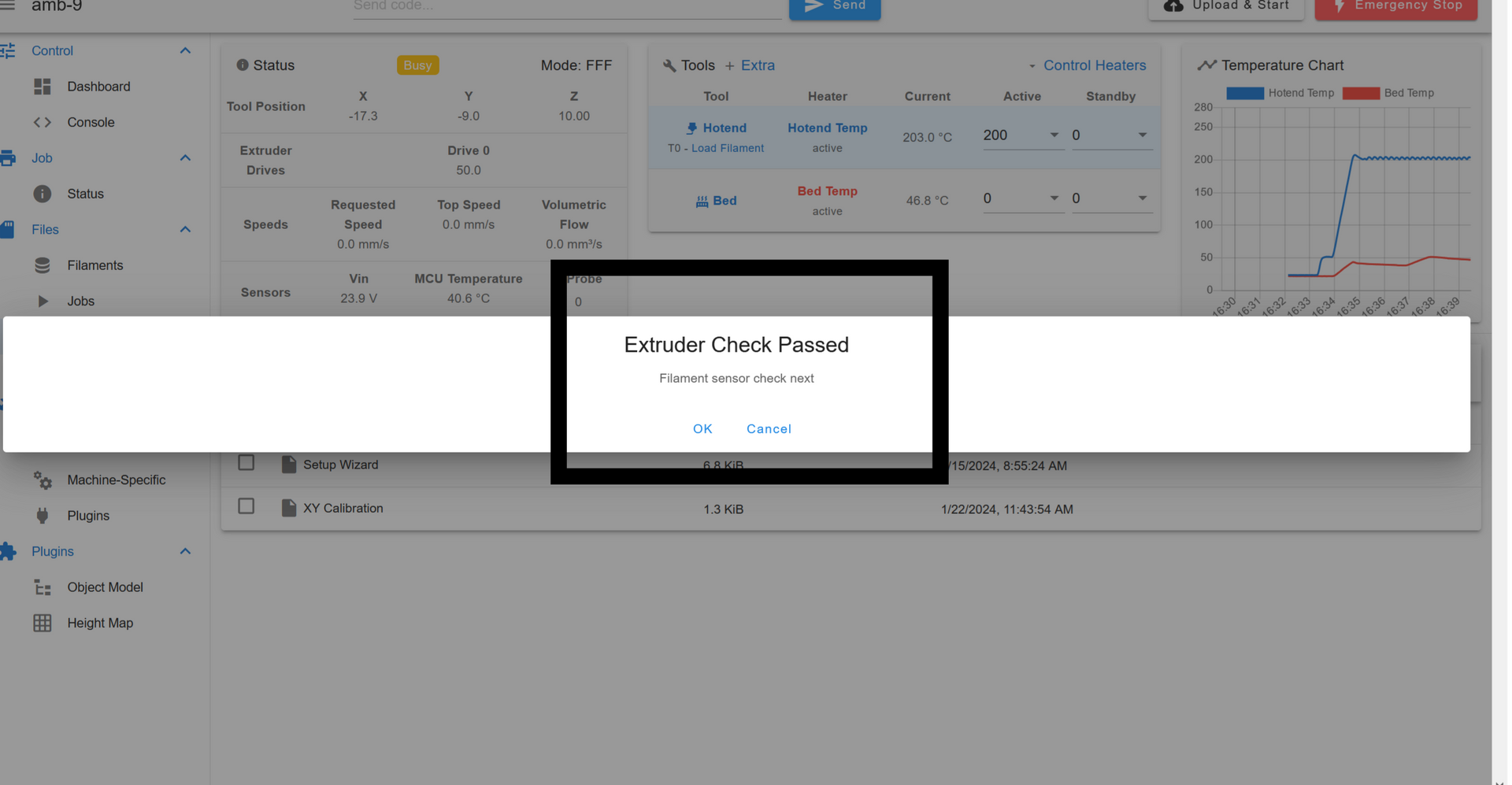
⬛ A message will pop up saying the extruder check is complete.
- Clear the next message to go to the next section.
Step 11: Setup Wizard pt. 6- filament sensor


🟪 A message will pop up asking you to remove the filament from the extruder.
🟦 Push the extruder lever to the open position.
🟩 Pull the filament out of the extruder.
- The light on the filament sensor should come on.
🟨 Clear the instruction message.
- An event notification should take it’s place saying that a filament out was detected.
❌If the light does not come on and the event notification does not appear then there is a wiring issue with the sensor.
If the light comes on but there is not an event notification then there is an issue in the config.g or the sensor is plugged into the wrong port on the Duet.
🟧 If the event notification did appear, clear it.
🟥 It should be replaced by a message asking if the notification worked.
- Clear it to go on to the next section.
Step 12: Setup Wizard pt. 7- part fan


🟪 The part fan should turn on.
🟦 Confirm this by either looking under the distal arm or touching the fan.
⚠The hotend is likely still hot at this time.
- If the fan is on confirm.
🟩 Clear the next message to go to the next section.
Step 13: Setup Wizard pt. 8- BLTouch


🟪 The BLTouch probe should deploy.
- The probe pin will extend.
- The red light in the BLTouch will turn off.
🟦 Confirm if the probe deployed.
❌If the probe did not deploy
- Check the connections. There may be an issue with the wiring.
- The BLTouch may simply have a bad connection to the Duet, not necessarily that something is incorrectly wired.
- The BLTouch may simply have a bad connection to the Duet, not necessarily that something is incorrectly wired.
- The BLTouch could be connected to the wrong port on the Duet.
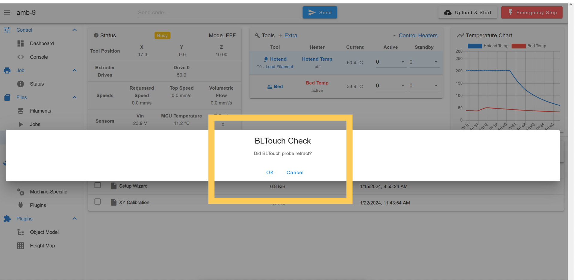
🟩 The probe should retract.
- The pin will retract.
- The red light will turn back on.
🟨 Confirm the BLTouch is working.
❌If the BLTouch deployed but did not retract.
- The BLTouch could have a weak connection with the Duet.
- It’s possible there is an error in the setup files for the BLTouch in the Duet.
- If the BLTouch retracted confirm the message to go to the next section.
Step 14: Setup Wizard pt. 9- homing


🟪 A message will appear notifying that the printer will home after the message is cleared. Read this sequence before clearing the message.
What should happen:
- Z axis moves up.
- Both joints move towards endstops.
- Joints stop once they reach endstop.
❌If the joints don’t stop they will error out the drivers, you can see this has happened if a red light starts flashing on the driver.
- Proximal arm moves away from endstop and back to it.
- Distal arm moves away from endstop and back to it.
- Arm moves to the center of the bed.
❌If the arm moves somewhere else there is a problem in the config file
- BLTouch is deployed
- Z moves down to bed.
- Z stops once BLTouch hits bed.
❌If the BLTouch does not touch the bed before the nozzle or the BLTouch does not stop the Z then the printer will try to bury the nozzle in the bed. Hit the E-stop button in the UI.
- Z raises up and deploys BLTouch again.
- Z lowers to bed a second time until the BLTouch stops it.
- Z moves up and arm moves to the side of the bed.
🟦 If something in this sequence does not happen, hit the E-stop button in the UI or flip the power switch on the back of the printer off.
🟩 If this sequence happened correctly confirm on the next message.
🟨 Clear the next message to go to the next section.
Step 15: Setup Wizard pt. 10- Z calibration


🟪 A message will pop up and the arm should move the hotend to the center of the bed, just above the bed surface.
- Clear notification message.
🟦 A message will pop up with a jog panel.
🟩 Jog the nozzle up or down until the nozzle is barely touching the bed.
- Take the value the Z shows when the nozzle is touching the bed and write it down.
- This will be used after the setup wizard.
- Clear the jog panel.
🟨 Clear the next message to go to the next section.
Step 16: Setup Wizard pt. 11- XY calibration


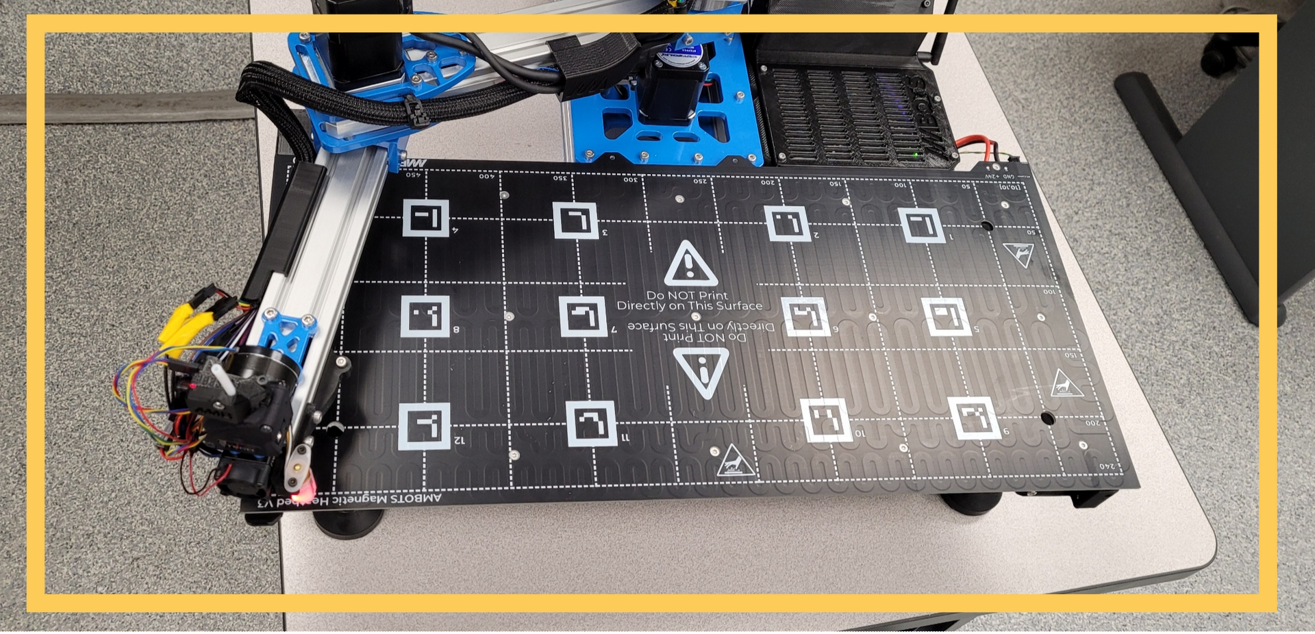


⚠Take the bed surface off the printer for these next couple sections.
🟪 A new message will appear and the nozzle will move to the corner of the bed by the circuit case.
🟦 Clear the notification message.
- A jog panel will appear.
- jog the nozzle around so that the center of the nozzle is directly over the corner of the bed.
- Take a note of the XY values for later.
- Clear the jog panel message.
🟩 A notification will appear and the hotend should move up and then away from the circuit case to the next corner.
- Clear the notification message.
- A jog panel will appear.
- jog the nozzle around so that the center of the nozzle is directly over the corner of the bed.
- Take a note of the XY values for later.
- Clear the jog panel message.
🟨 A notification will appear and the hotend should move up and then to the next corner.
- Clear the notification message.
- A jog panel will appear.
- jog the nozzle around so that the center of the nozzle is directly over the corner of the bed.
- Take a note of the XY values for later.
- Clear the jog panel message.
🟧 A notification will appear and the hotend should move up and then to the fourth corner.
- Clear the notification message.
- A jog panel will appear.
- jog the nozzle around so that the center of the nozzle is directly over the corner of the bed.
- Take a note of the XY values for later.
- Clear the jog panel message.
🟥 Clear the next message to go to the next section.
Step 17: Setup Wizard pt. 12- BLTouch XY Calibration


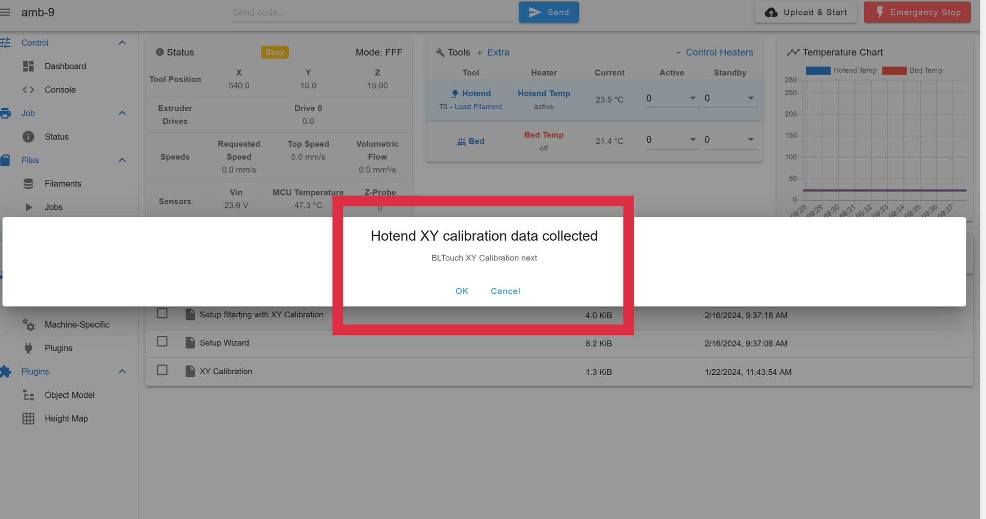
🟪 This is a repeat of step 15, except now you should align the BLTouch probe to the points on the PCB.
🟦 After the section is done a message will pop up saying that the Heater Tuning section is next. Put the print surface back on the printer before clearing the message.
Step 18: Setup Wizard pt. 12- Heater Tuning


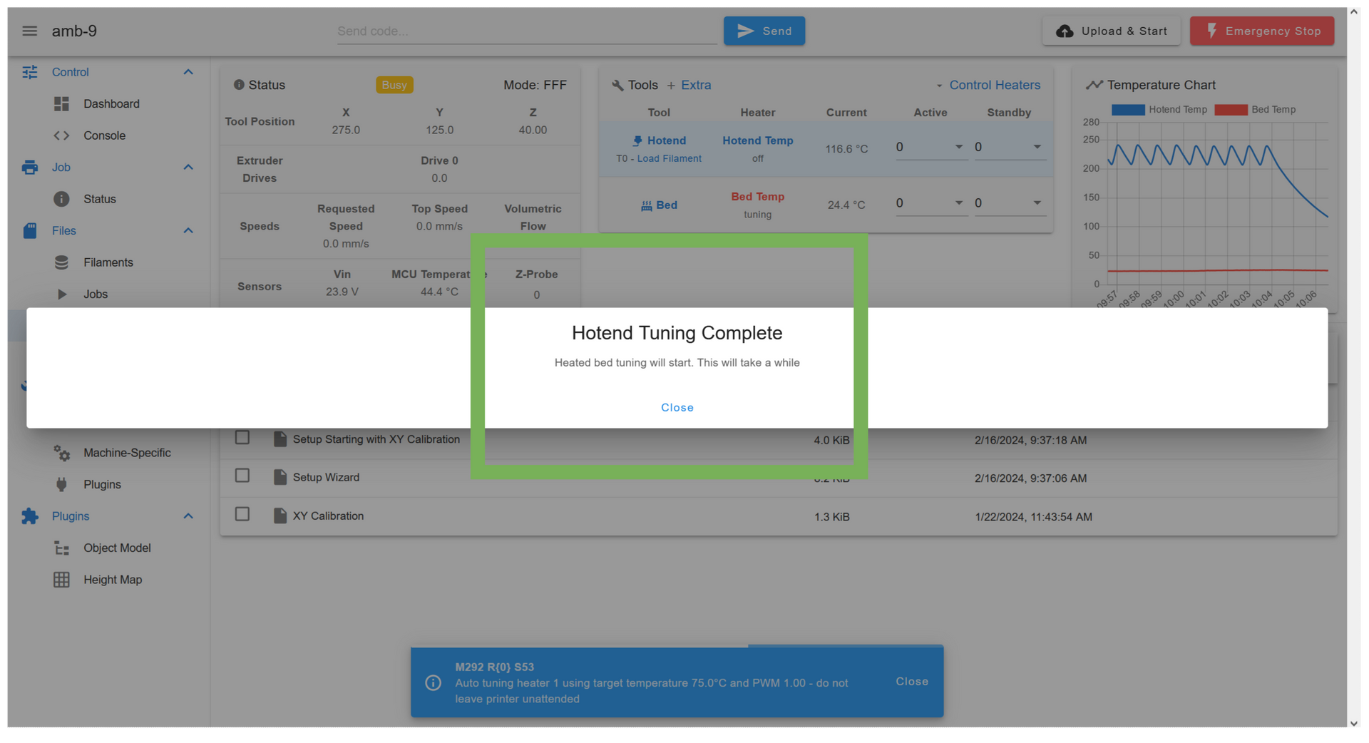

🟪 A message will pop up notifying that hotend tuning will start.
- Arm will move to the center of the bed.
❌The nozzle should not be touching the bed at this time. Cancel the wizard and restart the printer.
You will need to put in the Z height calibration number first.
- The hotend heater will turn on and start tuning.
- This can take 15 minutes. Don’t leave the printer, but you don’t have to watch it closely, just keep the Duet UI open and keep an eye for any error messages.
- Clear the notification message.
🟦 After tuning is finished a message will come up asking if you want to save the tuning to the config.
- Confirm the save to config.
🟩 A new notification message will appear that heated bed tuning will start.
- The z axis will move up.
- The heated bed will turn on and start tuning.
- This will take a while. Don’t leave the printer, but you don’t have to watch it closely, just keep the Duet UI open and keep an eye for any error messages.
🟨 After tuning is finished a message will come up asking if you want to save the tuning to the config.
- Confirm the save to config.
Step 19: Setup wizard complete

🟪 After the notification goes away it should be replaced by a message saying the setup wizard is complete.
- Clear this message.
Step 19: Inputting the Z height value

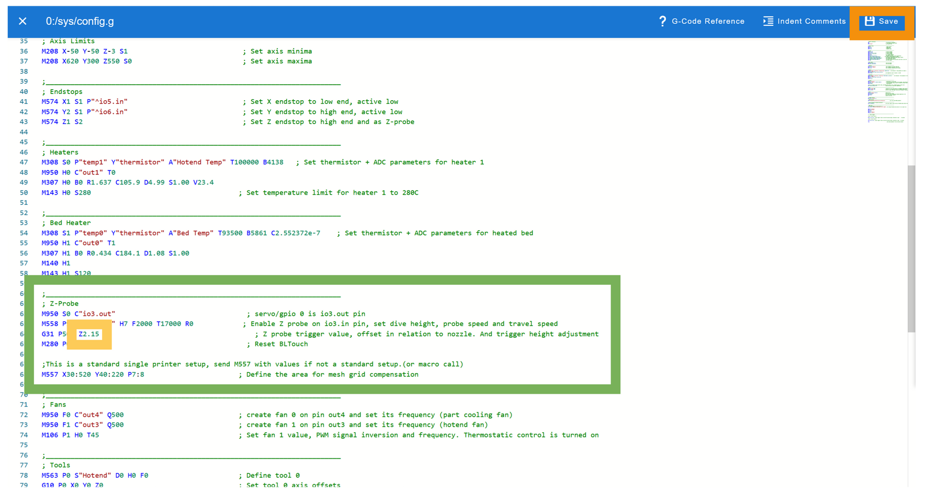
🟪 In the Duet UI, go to the “System files” tab
🟦 Open the config.g file.
🟩 There is a section titled “Z-probe”, go to the G31 command in it.
- Take the Z value you took note of in step 14
- subtract the value from the Z value in the G31 command.
- Example, if you wrote down a value of 0.5, the Z value would now be:
- Z=2-0.5=1.5
- Z=2-0.5=1.5
- Example, if you wrote down a value of -0.5, the Z value would now be:
- Z=2-(-0.5)=2.5
- Z=2-(-0.5)=2.5
🟨 Change the Z value in the G31 command to the new one.
🟧 Save the config.g file.
Step 20: Calibrating the Hotend XY


- This step requires that you have setup the hub and UI. If not, come back to this after you get the other systems running.
🟪 Open the “printer calibration” panel in the UI.
🟦 Enter in the printer ID number in the top box.
🟩 Enter the point coordinates you gathered in the point boxes in the order you gathered them.
🟨 Click on the gear icon to go to the parameters section.
- You can check whether the points you input match the corners of the bed of the target points.
- You can also shift the output calibration by inputting into the offset and rotation boxes.
🟧 Select whether the values correspond to the BLTouch or hotend.
🟥 Click the “Calibrate” button.
- The UI will output a response when the hub finishes the calculations with the final error and calibration command.
- The command is saved to the printer, the command in the console is just for reference.
- The error is the solver error in calibrating the printer. An acceptable error is under 1, and a good error is under 0.5.
Step 21: Calibrating the BLTouch XY


- Repeat the process in step 20, but with the XY coordinates you gathered for the BLTouch.
🟪 After you have the output config from the Excel file, go to the bltouch_configuration file in the macros tab.
🟦 Paste the output into the file.
🟩 Save the BLTouch configuration.
Step 22: Bed leveling


🟪 Go back to the “Printer Setup” folder in the “Macros” tab.
🟦 There is a file labelled “Manual bed level”
- Run this file.
🟩 The arm will move to the corner by the circuit case and a jog panel will appear.
- Move the Z down until the nozzle touches the bed, take note of the value.
- Press “ok” on the jog panel to continue.
🟨 The arm will move to the next corner and another jog panel will appear.
- Move the Z down until the nozzle touches the bed, check the Z value, it should be close to the previous value (+/- 2mm)
- If the Z value is more than 2mm off of the previous value, move the Z up and try to adjust the leveling foot under that corner of the bed up or down until you can get the Z value the nozzle touches the bed at within 2mm of the previous value.
- If the Z value is more than 2mm off of the previous value, move the Z up and try to adjust the leveling foot under that corner of the bed up or down until you can get the Z value the nozzle touches the bed at within 2mm of the previous value.
🗈You may need to loosen the set screws attaching the bed to the arm if you need to make larger adjustments, just make sure to re-tighten the set screws once you are done.
- Once you are done adjusting this corner, press the “OK” button on the jog panel to go to the next corner.
🟧 Repeat the previous instruction for the next two corners.
- Try to get each corner as close as possible to the first corner.
🟥 After pressing “OK” after the fourth corner, a new message box will appear saying the arm will run automated bed leveling to check your work.
- Press the “OK” button on this message to start bed leveling.
- The arm will run it’s bed leveling script, but just checking the four corners of the bed.
⬛ After bed leveling is done, go to the “Height Map” tab in the Plugings section of the Duet UI.
🗈If the “Height Map” tab isn’t shown, go to the plugins list to start it.
- This shows an exaggerated representation of the height data gathered by the bed leveling.
- Look at the “Maximum Deviations” line in the statistics section of the page.
- The deviation should be within -2mm / 2mm
- If not, you may want to repeat this step to improve the leveling.
- The deviation should be within -2mm / 2mm
The automated bed leveling can compensate for a much larger deviation across the bed than +/- 2mm, but the first layer quality will decrease and it will effect the flatness of cooperatively printed parts.
⚠Make sure you re-tightened the set screws between the bed frame and the arm base before continuing.
Step 23: Test print

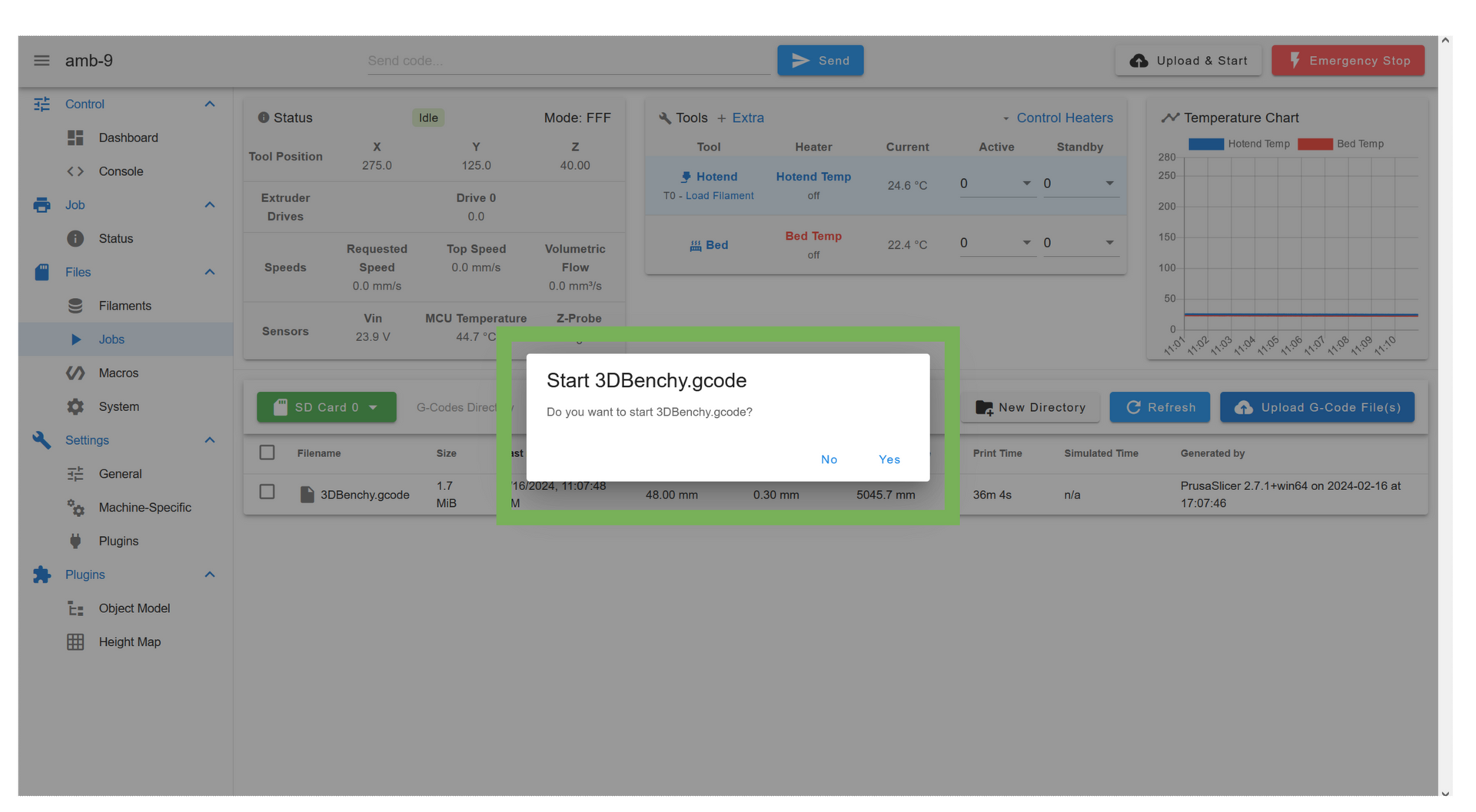


🟪 Go to the “Jobs” Tab in the Duet UI
🟦 There should be a preloaded gcode file
🟩 Select it and start the print.
🟨 The Duet UI should go to the status page, and the heaters should start heating up.
🟧 When the print finishes bed leveling you may need to jog the nozzle up or down on the status page.
- Watch the print for the first layer or two (this test print will be fairly short)
🟥 Let the print run until something goes wrong or the print finishes.
Step 24: All Done

- Congratulations! You’ve successfully assembled a printer! 🎉

